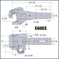
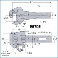
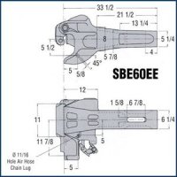
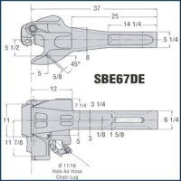
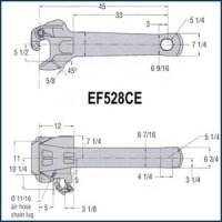
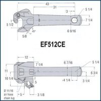
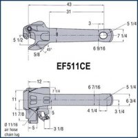
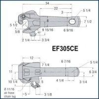
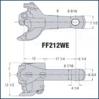
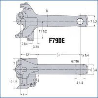
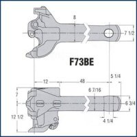
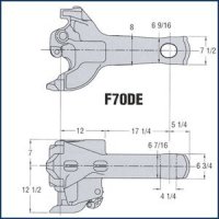
Freight Coupler

FREIGHT COUPLERS

AAR & DOT SHELF COUPLERS
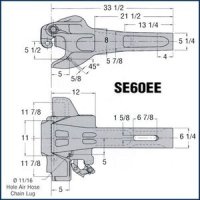
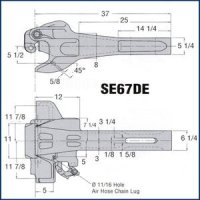
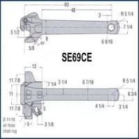
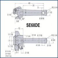
All hazardous material cars must be equipped with couplers having top and bottom shelves projecting from head end front faces. The purpose of the shelves is to prevent vertical coupler disengagement during train derailment and thereby minimize the potential for tank car shell puncture. All AAR standard E, E/F and F couplers are available with top and bottom shelves. These are identified by prefixes to the coupler catalog numbers as follows:
SE – Double Shelf (Top & Bottom) E and E/F Couplers
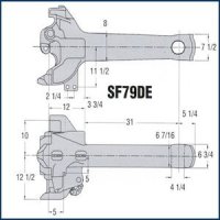
SF – Double Shelf (Top & Bottom) F Couplers
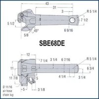
All new and rebuilt cards must be equipped with couplers having a bottom shelf as a minimum requirement. The bottom shelf serves to support a mating coupler suffering a pull-out from car sill and this keeps it from falling to the roadbed and presenting a derailment hazard. The shelf also serves to prevent vertical coupler disengagement during derailment, as related to the mating coupler. The bottom shelf is effective when the 10-A contours of the mating couplers are within AAR specified condemning limits. Bottom shelf couplers are identified by prefixes:
SBE – Bottom Shelf E Couplers
COUPLER TYPES
FREIGHT CAR TYPE E COUPLERS
All Type E couplers are equipped with head ends of an identical “basic” design. It is this “basic” head design that is designated as Type E.
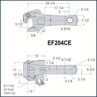
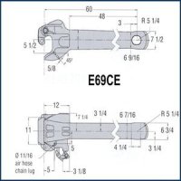
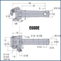
To meet varied service condition arrangement needs, Type E couplers may be equipped with variant compatible shank designs and special features for fitting. For purposes of identification, each different coupler design is indicated by the assignment of a Catalog Number or ID number. Modifications to existing designs are indicated by the assignment of suffix letters to coupler Catalog Numbers or ID Numbers.
All Type E couplers are furnished with bodies, knuckles and locks of quenched and tempered Grade E steel. Grade E material is identified by the letter E at the end of the item Catalog number, or ID Number.
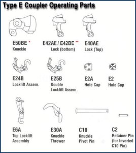
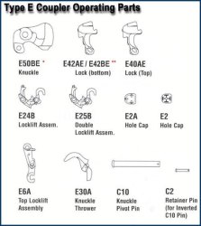
All of the Standard operation parts are interchangeable from one Type E or E/F coupler to another; except when the locklift arrangement precludes change in design of the locklift assemblies. The Type E operating parts are designed so that they will not fit into other Types of couplers, except as listed.
TYPE E COUPLER PARTS LIST
TYPE E COUPLERS AND PARTS ARE GOVERNED BY THE FOLLOWING AAR SPECIFICATIONS AND INTERCHANGE RULES:
- M-118 Knuckle Pins & Shank Connecting Pins
- M-201 General for Steel Castings
- S-172 Inspection & Maintenance on Cars
- M-211 Purchase & Acceptance
- M-212 Secondhand & Reconditioned
- Rule 16 Type E Couplers & Parts
- Rule 19 Yokes for Type E Couplers
- Rule 88 Couplers & Parts Required for Car Acceptance
- Rule 90 Couplers & Parts Prohibited in Interchange
FREIGHT CAR TYPE E/F COUPLERS
All Type E/F couplers are equipped with the Type E coupler “basic” design E head and one of the “basic” designs of the Type F coupler shanks and butt ends.
To meet varied service equipment arrangement needs, Type E/F couplers may be equipped with variant compatible shank designs and special features or fittings. For purposes of identification, each different coupler design is indicated by the assignment of a Catalog Number or ID No. Modifications to existing designs are indicated by the assignment of suffix letters to coupler catalog numbers or identification numbers.
Type E/F couplers have the same operating parts as the Type E couplers. Coupler yoke connection consists of the vertical pin (Y47) Type F; or a compatible end of car (EOC) cushioning device.
FREIGHT CAR TYPE F COUPLERS
Type F interlocking couplers are equipped with the F design head end and the F design shank and butt end. Incorporated into the F design are several features that are not available in the Types E and E/F designs. These added features include:
- Frontal interlocking wing pockets and lugs that interlock with any mating interlocking coupler. These safety features help maintain the couplers and derailed cars in alignment to assist in preventing over-turning and telescoping of the cars.
- A frontal bottom support shelf is standard on all F couplers to prevent a mating pulled out coupler from falling to the roadbed and thereby becoming a hazard.
- A total of only 3.8” of free contour slack exists between two new F Interlocking couplers: as opposed to 25/32” for two new Type E or Type E/F mated couplers. The result is an improvement in train handling actions.
- Reduction in wear on head surfaces results in extended services life due to control of vertical interface movements and less free contour slack.
- Buff loads are distributed through the central column of the F Interlocking coupler.
- When provided, the shank butt alignment shoulders assist in keeping the couplers centered and cars aligned under heavy buffing actions and slack run-in.
- The vertical pin connection makes a more efficient assembly than possible with a crosskey
- Coupler locklift assembly provides a telltale visual means for determining that the coupler is securely locked.
- A three-way anti-creep feature prevents accidental uncoupling of the rotary bottom operating Type F Coupler.
All of the Standard operating parts are interchangeable from one Type F coupler to another, except when the locklift arrangement precludes change in design of the locklift assemblies. Type F operating parts are designed so that they will not fit into other Types of couplers, except as listed.
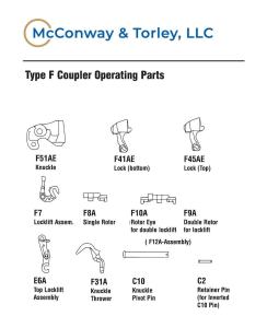
TYPE F COUPLER PARTS LIST
TYPE F COUPLERS AND PARTS ARE GOVERNED BY THE FOLLOWING AAR SPECIFICATIONS AND INTERCHANGE RULES:
- M-118 Knuckle Pins & Shank Connecting Pins
- M-201 General for Steel Castings
- S-172 Inspection & Maintenance on Cars
- M-211 Purchase & Acceptance
- M-212 Secondhand & Reconditioned
- Rule 16 Type E Couplers & Parts
- Rule 19 Yokes for Type E Couplers
- Rule 88 Couplers & Parts Required for Car Acceptance
- Rule 90 Couplers & Parts Prohibited in Interchange
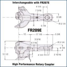
FR209E AAR APPROVED HIGH PERFORMANCE ROTARY COUPLER SYSTEM
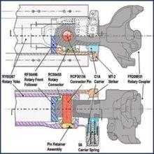
Rotary couplers are equipped with the F-head design with an innovative rotary shank and connection. The rotary shank design allows the coupler to revolve a full 360 degress within the specially designed rotary yoke, which along with all of its interior components, is also available from M&T. The rotary system has several innovative features to add value and longevity to your car.
- Coupler and yoke assembly will fit in a standard car pocket and use a standard Type F striker and carrier. There is no need for specialty car construction with these parts, so they can be interchanged with standard F couplers and yokes as needed depending on the usage of the car.
- Coupler butt ends are flame-hardened to reduce wear and extend coupler life.
- Type F coupler head is standard and takes standard parts. The same knuckles and pins can be used in each end of the car.
- Anti-gravity lock keeps coupler from becoming unlocked during rotary operation.
- The rotary follower block uses a centering design which works with the butt end design of the coupler to keep the coupler butt correctly aligned in the pocket.
- The rotary shank has a cross section designed to provide smooth rotary action and eliminate binding during operation.
- The rotary shank has a larger cross-sectional area than a standard F-type coupler, increasing life of the coupler.
All Rotary couplers have the standard No. 10-A contour at coupler mating lines. This contour includes all external vertical faces of the knuckle and coupler front faces and guard arm faces that meet and engage with an opposing coupler to coupler adjoining cars. Rotary couplers will couple with all other couplers in Interchange service.
Due to the necessity of the anti-gravity lock, Rotary Couplers cannot be fitted as Top Operating couplers. All Rotary Couplers will be supplied as Bottom Operating. With the exception of the anti-gravity lock, all other standard operating parts are interchangeable with standard F-type couplers.
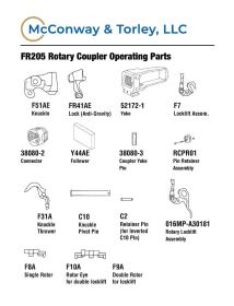
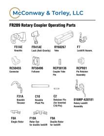
ROTARY COUPLER PARTS LIST
MCCONWAY & TORLEY HIGH PERFORMANCE ROTARY COUPLER SYSTEM
- FR209E01 Coupler Complete Flame hardened butt and pin area
- RY60267 “F” Type Rotary Yoke
- RCP30136 3 3/4″ Connector Pin
- RF50496 “F” Type Rotary Follower
- RC50455 Rotary Connector
- RCPR01 Pin Retainer Assembly
MCCONWAY & TORLEY STRIKER ASSEMBLY
- MT-2 Striker
- C1A Carrier
- S6 Carrier Springs (3)

DROP US A LINE
................................................... ...................................................
QUALITY RAIL PARTS AND EQUIPMENT
MARKET-LEADING EXPERTISE, PRODUCT, AND SUPPORT.
